AN/ALR-67 RWR Radar Waning Receiver
| Site: | Open Flight School |
| Course: | F/A-18C Hornet Weapon Basic Course (DCS) |
| Book: | AN/ALR-67 RWR Radar Waning Receiver |
| Printed by: | Guest user |
| Date: | Wednesday, 18 March 2026, 9:13 PM |
1. Radar Warning System
The F/A-18C is equipped with an ALR-67(V) Radar Warning System. This system detects the radiation of the aircraft by other radar systems and warns the pilot. Infrared guided missiles are not detected. That means an approaching missile without an associated radar warning is definitely an IR missile. However, it is of course possible that an enemy aircraft has radar tracked you and is firing an IR missile at you.
To do this, open MISSION > F/A-18C > Training Mission - Defensive Systems (Caucasus, Nevada or Persian Gulf).
There are several cockpit elements that belong to the Radar Warning System:
- Radar Warning Display
- Control PPanel for the Countermeasures
- EW page on the DDI
- Warning and Information Lights
- HUD Warnings and Indiations
Radar Warning Display
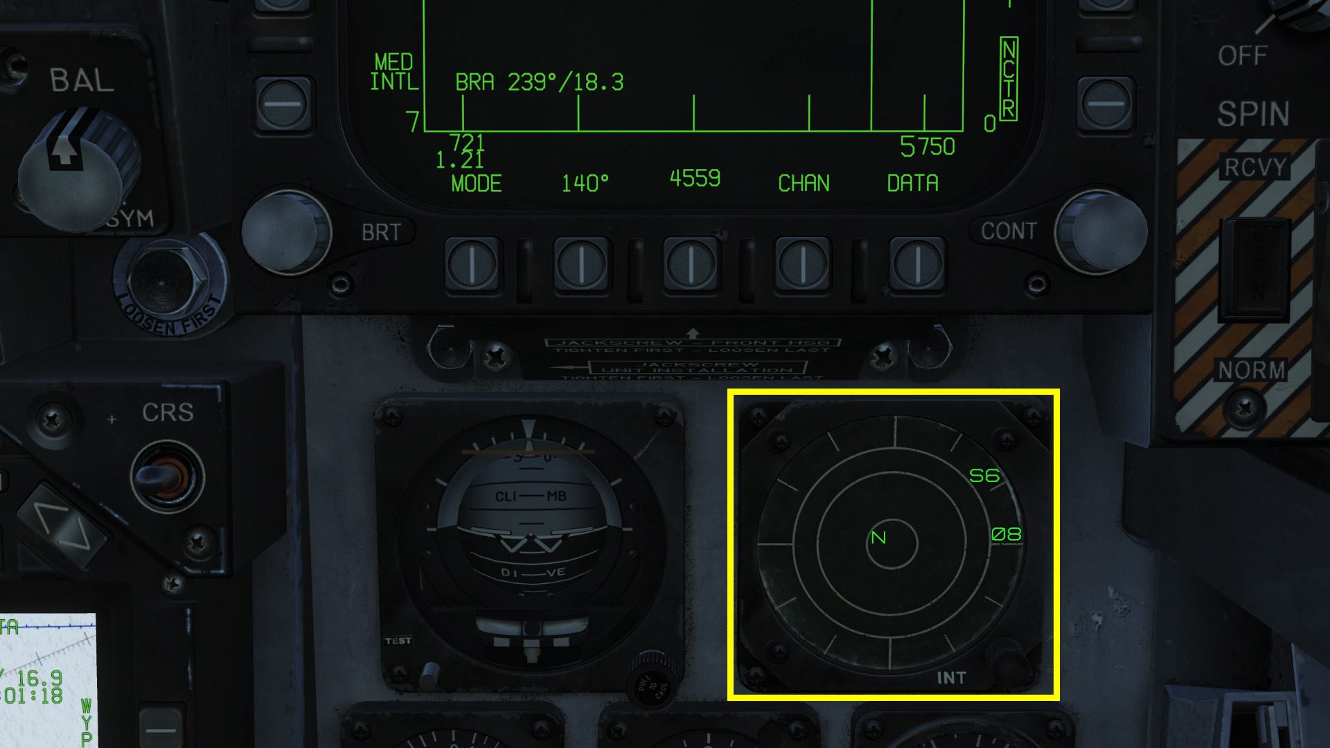
The Radar Warning Display (RWR) is a small display on the front right instrument panel below the right DDI. It shows our surroundings and the threats they contain.
In the middle is our plane and we view it from above.
 |
 |
The RWR is divided into zones from inside to outside by rings. Located radar sources are indicated by a symbol with the relative bearing.
In the example below, radar source 08 is approximately at our 3 o'clock position, i.e. In the direction of the right wing.
It is important to know that the distance between the centre of the display and the displayed radar source does not have any relation to the distance between our aircraft and the radar source.
More importantly, it represents the level of threat to our aircraft. The closer the symbol gets to the center, the more dangerous the radar source is for us..
Meaning of the Zones:
- Status Circle:
In the middle is the Status Circle. It symbolizes our airplane and shows different information by letters. - Critical Zone:
In this area the most dangerous enemy systems are displayed. - Dangerous Zone:
Threats displayed in the second ring have been classified by the system as potentially lethal. - Non-Dangerous Zone:
The outermost ring shows unidentified and friendly radar sources. If an enemy radar source is detected and classified as non-lethal, it is also shown in this zone.
Status Circle
The status circle is divided into three areas:
- Zone I: The area at the top left.
- Zone II: The area at the top right.
- Zone III: The lower area.
The EW mode priority setting (N, I, A, U or F) is displayed in the Zone I. This setting is selected on the EW page of the DDI or the Countermeasure Control Panel.
- Normal
- Intercept
- AAA -Anti-Aircrat Artiliery
- Unknown
- Friendly
The Zone II is empty when the full display mode is used. When switching to the limited mode, the letter L appears there.
At the bottom in Zone III, the BIT status is displayed.
If an error is found, the letter B is displayed.
If the countermeasure computer is thermally overloaded, a T is displayed there.
If there are no errors, the area remains blank.
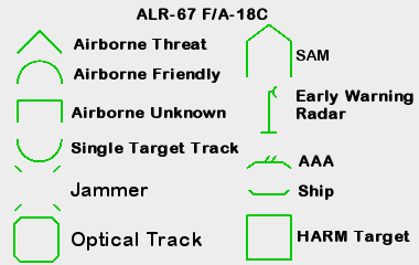
Symbols
When a radar source is detected, the system starts an analysis.
As soon as the source is identified, it is indicated by an alphanumeric code in the Radar Warning Display and on the EW page of the DDI.
The letter U stands for Unknown.
Here is a list (created by .408-X~RAY) of the possible symbols:
1.1. Control Indicator Panel
Below the AMPCD is the RWR Control Indicator Panel.
With it you can make the same settings as on the EW page of the DDI.
On the right side is the POWER button. It is used to turn the ALR-67(v) system ON and OFF.
The buttons light up when the system is turned on.
With the DISPLAY button a Limited Display mode can be activated, then only the 6 most dangerous radar sources will be displayed.
This is helpful if there are too many radar sources and you only want to see the most important ones.
If this mode is activated, the word LIMIT is also displayed in the button.
The SPECIAL button has not yet been implemented.
Pressing OFFSET button will separate overlapping symbols from each other. However, the bearing to the sources is then of course no longer accurate.
This function is also very helpful if there are many sources in a small area and you want to get a better picture of them.
If the function is activated, the word ENABLE is written in the button.
If you press the BIT button a Built-in-Test (BIT) status is displayed on the RWR. If there is an error, the word FAIL appears in the button.
Use the knob DMR to adjust the brightness with which the buttons light up. This is important for night lighting.
With the DIS TYPE rotary switch the display priority of the radar types can be set:
- N - Normal
- I - Intercept
- A - Anti-Aircraft Artillery
- U - Unknown
- F - Friendly
These are also displayed in the status circle of the RWR display in Zone I.
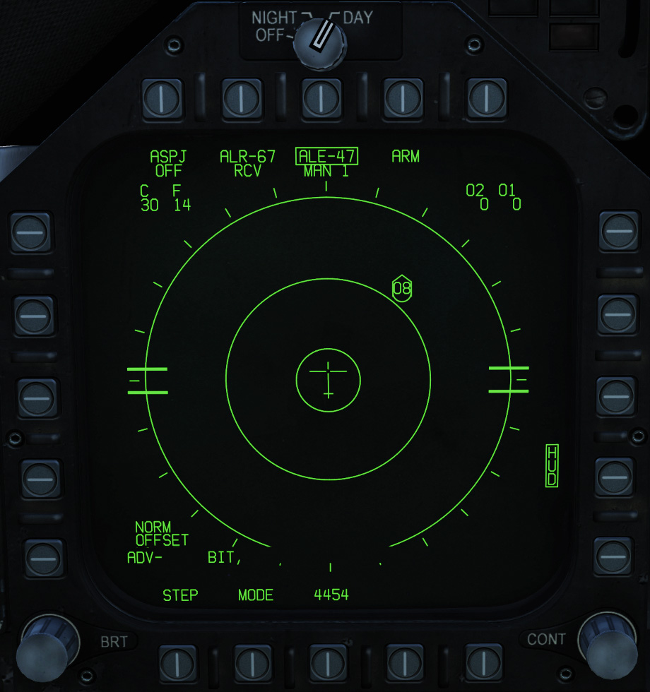
1.2. EW Page
The EW page (Electronic Warfare) has already been used intensively in the configuration of the countermeasures.
It also reflects the radar sources displayed at the RWR display.
In addition to the alphanumeric codes, the type of radar source is represented by a surrounding icon.
In Slysi's Western RWR Kneeboard the icons are explained in detail:
Some of the features are still missing. We will extend the description of these here later.
The status of the ASPJ (Airborne Self Protection Jammer) is displayed at the very top below the upper PBs.
Since the system has not yet been implemented in Early Access, OFF is always displayed here. Changes to its settings are not yet possible.
Second, the status of the ALR-67 radar warning system is displayed. Again, no settings can be changed.
The use of the ALE-47 and the corresponding keys have already been discussed.
Below this there are indicators for the number of countermeasures loaded. However, these are only displayed if ALE-47 is activated and is not in BYPASS mode.
- C - Chaff
- F - Flares
- O2 & O1 stand for GEN-X Decoys, but they also, are not yet implemented.
1.3. Warning Lights
On the right hand side of the front instrument panel are some warning lights associated with the ALR-67 Radar Warning System. On the left hand side the status of the BIT is displayed.
| Left Warning Light Field | Right Warning Light Field |
|
|
|
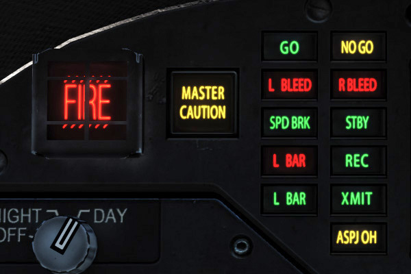
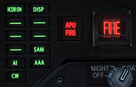
- AI:
Enemy radar in airborne intercept (AI) mode.
Shown in the critical zone. - CW:
Enemy radar in Continuos Wave (CW) mode.
Probably directing an air-to-air missile towards your aircraft and being displayed in the critical zone. - SAM:
Enemy surface-to-air radar that has detected your aircraft. This is displayed in the critical zone. - AAA:
Radar from an enemy anti-aircraft battery that has detected your plane. - DISP:
The ALE-47 has analyzed the threat in S/A mode and set a suitable countermeasure program.
In addition, the HUD displays the word DISPENSE. - GO / NO GO:
Result of the BIT from ALE-47 when the eject switch is set to ON or BYPASS.
1.4. Audio Warnings
Certain sounds are used to warn the pilot of threats. For example, if a new radar source is detected or a source changes to a more dangerous status, a warning tone is played.
If a source disappears or the threat decreases, no tone is played.
We will explain these sounds here:
- Status Change (StatusChange)
- Single 455hz tone with a duration of 0.335 seconds
- Shows the following:
- New Radar Source
- A radar source was moved from the safe to the dangerous zone
- A radar source was moved from the dangerous to the critical zone
- RWR BIT error
- Example:
- New Plane (Waterfall)
- Sequence of four tones in the following order. 550hz, 520hz, 490hz, 470hz. Each tone has a length of 0.083 seconds. The total length is 0.335 seconds.
- Played when a radar of an aircraft has been added
- Example:
- Radar Uplink (Missile Alert)
- A continuous tone that changes between 455hz and 555hz. Each tone has a duration of 0.25 seconds.
- Played when a station locks onto you
- Example:
- Missile Approach (MissileLaunch)
- A continuous tone that changes between 455hz and 555hz. But now the tone changes faster (only 0.1 seconds) than with radar activation.
- Example:
Source: https://forums.eagle.ru/showpost.php?p=3347570&postcount=7
1.5. HUD
We will add the description here later, as soon as the functions are available.