The Airfield: Structure, Traffic Rules and Procedures
| Site: | Open Flight School |
| Course: | Theory Basic Course |
| Book: | The Airfield: Structure, Traffic Rules and Procedures |
| Printed by: | Guest user |
| Date: | Saturday, 21 February 2026, 10:39 PM |
1. Construction of an Airfield
 Airfields are generally:
- Large area
- Access controlled
- Different sections with defined tasks
- Normally outside larger cities
- Civil, mixed or purely military use
Purpose. They serve for:
- Take-off and landing of aircraft and helicopters
- Aircraft maintenance and repair
- Parking area
- Transport of passengers and cargo
Large airfields are gigantic infrastructural projects with decades of use and considerable effects on the environment, the housing situation of local residents, the job market and the economic situation of entire regions. An airfield belongs to the public transport network just like a motorway or railway station.
Airspace. The airspace around the airport is subject to restrictions and special regulations. The military significance for logistics and defence of entire countries makes airfields primary targets in any conflict.
When viewed from the air airfields appear to be very clearly arranged. However, on the ground they are a tangle of paths, buildings and parking areas, so we would like to give you a few basics for orientation. The procedures at airports are actually logical and, in order to ensure smooth functioning, the same everywhere in the world. A few of the rules of conduct and procedures are very important for pilots and we will start with them in the second chapter.
1.1. Apron
 Apron. Primarily used as a parking area, the apron (or ramp, pan, dispersal) is located at the transition between the passenger area and the taxiways, runways and other areas closed to normal vehicle traffic.
The apron is usually a paved or concreted area. It is as large as a supermarket car park or larger than ten football pitches. Some airfields are so large that there are several aprons.
The typical use for aircraft is:
- Refuelling
- Parking
- Loading
For example, the typical holiday plane stands on the apron when passengers board. Either directly at a ramp or on a parking space where the passengers are taken by bus.
The airplane is prepared for the flight, the systems on board are started before being pushed back to taxi. Usually, having landed the aircraft taxi back here to shutdown.
As we cover different games and therefore different time periods here at the OFS, the aprons of airfields in different courses will also look different.
Examples from IL-2 Sturmovik
Here are examples from IL-2. The first is an unpaved airfield with several aprons. The airfield on the second has fixed concrete slabs and two aprons.
Examples from DCS
Now two examples of airfields in DCS. The first from the Caucasus Map (Anapa Vityazevo) and second from Normandy (Saint Pierre du Mont).
1.2. Taxiways
 Taxiways are the connection between the apron and the runways of an airport.
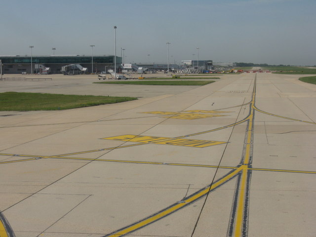
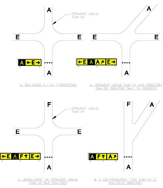
The taxiways of modern airfields are clearly numbered by letters and numbers. Normally there are yellow signs next to the taxiways at the crossroads of these routes, which mark the respective taxiways.
The taxiing of aircrafts is subject to approval by the tower or corresponding ground controllers who coordinate this part. Taxiways are one-way streets and are only used in one direction at a time. If used correctly by all parties involved, head on traffic can therefore never occur.
Examples from IL-2 Sturmovik
The following pictures show the taxiways on two IL-2 Sturmovik airfields.
Examples from DCS
The taxiways on two DCS airfields are shown here. Left from the Caucasus Map (Anapa Vityazevo) and right from Normandy (Saint Pierre du Mont).
1.3. Runway
![By WerWil [CC BY-SA 3.0 (https://creativecommons.org/licenses/by-sa/3.0) or GFDL (http://www.gnu.org/copyleft/fdl.html)], from Wikimedia Commons](https://commons.wikimedia.org/wiki/File:Startbahn_Oldenburg.JPG) The runway is well known by everyone. But very few of them will have stood on one with their own feet. The runway of a small airfield often consists of only one grass strip, while larger airfields usually have concrete runways. These can be more than 30 meters wide and between 5,000 feet and 7,500 feet long.
The runway is well known by everyone. But very few of them will have stood on one with their own feet. The runway of a small airfield often consists of only one grass strip, while larger airfields usually have concrete runways. These can be more than 30 meters wide and between 5,000 feet and 7,500 feet long.
The runway is usually labeled with two numbers at the beginning of the runway for better identification from the air. Multiplied by a factor of 10, these give the compass orientation of the runway in magnetic heading, which is accurate to 10 degrees. The exact orientation can be read from the airport plans.
According to the wind, planes take off in one direction or the other, so that they have the wind from ahead.
If there are several runways in the same direction, they are named Left or Right (see picture below IL-2).
Examples from IL-2 Sturmovik
The following pictures show the runways of two airfields from IL-2 Sturmovik.
Examples from DCS
The runways on two DCS airfields are shown here. Left from the Caucasus Map (Anapa Vityazevo) and right from Normandy (Saint Pierre du Mont).
1.4. Airspace
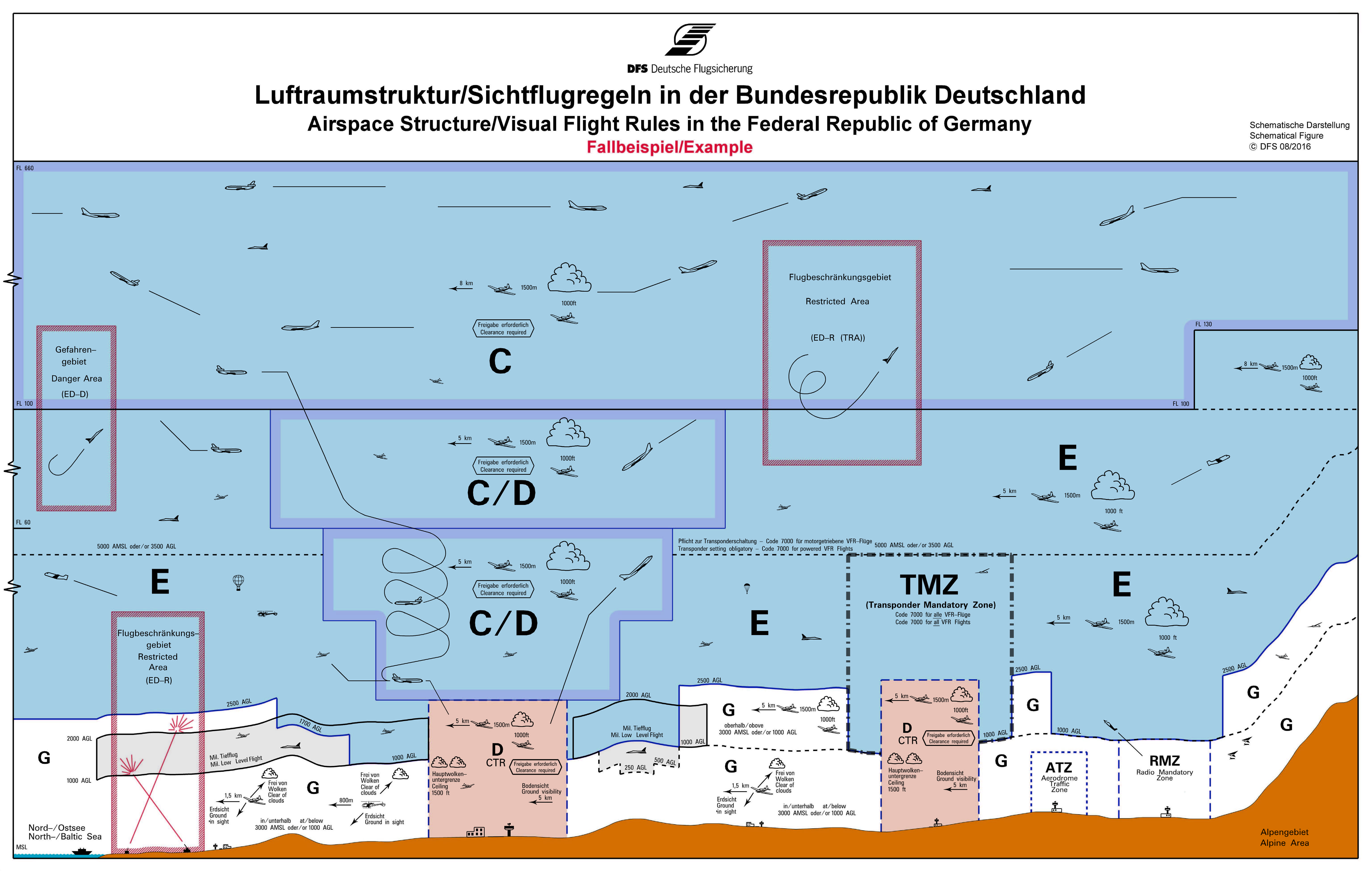
Applicable in Germany, landowners have not only the right to their land but also the right to the airspace above it and so every owner can prohibit the overflight. So rules are necessary, otherwise flying as we know it today would not be possible at all. The first rule is that the owner of the property can only decide about his airspace up to a height of 100m above the ground if nothing else has been determined. For everything that is higher, the landowner is deprived of his say by the state. (100m value applies to Germany, other states have similar rules)
The sky over Germany and everywhere else in the world is divided into zones and it requires permission to fly in these zones. A zone is clearly defined both in the area height and can also overlap with other zones. The definition is made by air traffic control and depends on things worthy of protection, such as industrial buildings or nature reserves as well as purpose.
There are certain requirements and traffic rules for the use of each individual airspace. Some can only be used under the Instrument Flight Rules (IFR) and for each airspace there is also a responsible airspace control (usually air traffic control e.g. by the controllers in the tower or radar room) which coordinates all aircraft movements within the zone. Each pilot must therefore make contact with the competent authority before entering an airspace. This alone means that a pilot cannot simply take off as he pleases.
Wide parts of the lower airspace are Class G and thus uncontrolled airspace, here roughly speaking everybody can fly "as he wants". However, an airfield is usually directly surrounded by a Class D airspace from the ground up and can therefore no longer be flown, taken off or landed without air traffic control permission. The controller in the tower is responsible for controlling this. He coordinates who takes off when and from where, so that there are no accidents.
This topic is very important for civil aviation, while military aviation usually takes place in a closed off airspace anyway. More about this later in theory for advanced users and especially X-Plane pilots.
1.5. QNH and QFE
General Information About the Barometric Altimeter
The Barometric Altimeter is based on setting an air pressure. Since the air pressure is not the same at every location, depending on the weather conditions (high and low pressure areas), it must be set for the current location. The value set should corresponds to altitude zero.
The barometric altimeter thus determines the current altitude via the measured air pressure (which decreases with increasing altitude).
In aviation, the two most important values for setting the altimeter are QNH and QFE. These so-called Q-groups originate from the time of the Morse codes.
- QNH: The air pressure relative to the sea level at the current location. I.e. the pilot sets the QNH, he shows the altitude above sea level at the current location. As a mnemonic, you can remember "Nautical Height."
- QFE: The air pressure at the current location. If the QFE pressure is set, then zero altitude is indicated for the current location. "Field Elevation" helps to remember.
- QNE: Not used by the International Civil Aviation Organization (ICAO) and not mentioned in the German Aeronautical Information Publication. In some countries it is defined differently. It corresponds analogously to the ISA (see below). Since the ISA is defined globally, it should be used preferentially. You can use the mnemonic "Not Equal", because the value (unlike the ISA) is defined differently in different countries.
As a rule, the QNH is always used in civil aviation.
Units of measurement
Europe is Hectopascal (hPa), USA it is Inches of Mercury (inHg, mercury), Russia it is millimetres of Mercury (mm, mercury).
1 inHg = 33.86 hPa
Standard Pressure
The ISA (International Standard Atmosphere) is an atmospheric model defined by the ICAO (International Civil Aviation Organization) with fixed values:
| Pressure at sea level: | 1013.25 hPa or 29.92 inHg or 760 mmHg |
| Temperature at sea level: | 15°C |
| Air density at sea level: | 1.226 kg/m³ |
| Relative Humidity: | 0% |
| Temperature decrease: | 2°C per 1,000 feet |
The ISA represents a mean value that all aircrew must use above a certain altitude. This uniform setting greatly simplifies the coordination between controllers and pilots and minimizes the risk of collision.
If pilots were to fly permanently with their QNH assigned by the airport, it would be possible for the altimeters of two aircraft to show different values even though they are at the same altitude.
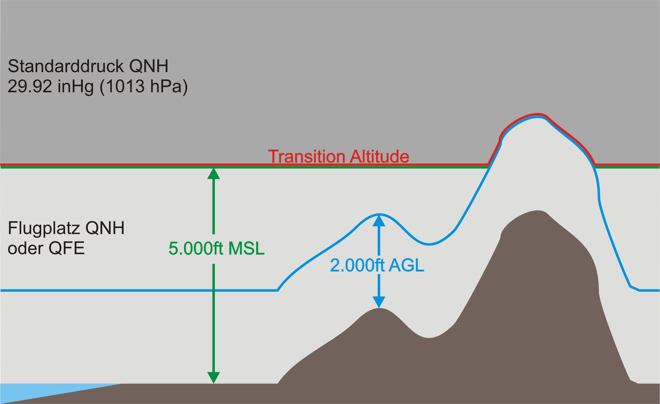
Transition Altitude, TA (transition altitude)
The Transition Altitude (when climbing) is the point to set ISA 29.92 inHg (or 1013 hPa / 760 mmHg) but is defined differently in each country. Here are some examples:
| Germany | 5,000 feet MSL |
| Austrian range | 10,000 feet MSL |
| USA | 18,000 feet MSL |
| England | 3,000 feet MSL |
In Germany, the standard pressure must be set to 29.92 inHg or 1013 hPa from 5,000 ft MSL upwards.
If 2,000 ft AGL is higher than 5,000 ft AMSL, 2,000 ft AGL is used as the TA.
Below TA height is refered to as "Altitude" and above TA it as a "Flight Level" or in the military range of Angels.
The flight level is always indicated in 100 ft.
Example: FL 300 corresponds to 30,000 feet. FL 255 corresponds to 25,500 feet. FL 253 is invalid, because it is out is the 500 steps.
Whereas Angels will indicate in 1,000 feet.
Example: Angels 30 corresponds to 30,000 feet
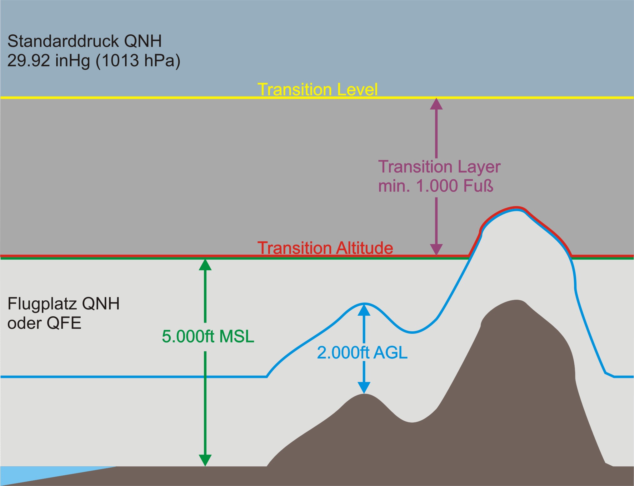
Transition Level, TL
The opposite of the transition height is the transition level. This applies to aircraft in descent. The TL is always at least 1,000 feet higher than the TA. The space in between is called the Transition Layer.
The TL is variable and depends on the prevailing air pressure, but as already mentioned, at least 1,000 feet higher than the TA.
Normally the TL is announced by the ATIS (Automatic Terminal Information Service).
Why must the TL now be higher than the TA?
Assume an aircraft sinks from high altitude at standard pressure from 29.92 inHg to 5,000 feet and now changes to the actual air pressure of QNH 28.32 inHg. The altimeter now shows 3,500 feet instead of 5,000 feet. This means that with ascending and descending aircraft, the TA overlaps. To prevent this, the TRL is always higher than TA and the lower the actual QNH at the airfield, the higher the TRL. In our example, the TRL would have to be 7,000 feet so that you are still over 5,000 feet when switching to the Airfield QNH.
Transition Layer
The transition layer between TA and TRL is called the transition layer. Logically, this layer is always at least 1,000 feet in size.
More information:
2. Airport Procedures
In Chapter one we have taken a rough look at the structure of an airfield/airport and here in Chapter two we want to take a closer look at individual airfield procedures and explain the background why certain things are done in a particular way and not differently.
In the cockpit pilots have to observe the technical specification of their respective aircraft; making the selections at the right time to operate the aircraft correctly. This is primarily internal to the cockpit and so is a separate topic. We will go into the theory of cockpit procedures later in more detail within the course for each aircraft. However, there are standard airfield procedures and rules of conduct that are the same for all aircraft at every airfield to ensure safe operation of the airport for all users.
What are standardised procedures good for? By following standard procedures every pilot’s behaviour becomes predictable and safe, minimising confusion between aircraft at the airfield.
2.1. No Movement Without Permission
We already know some information from the introduction to the topic of airspace. Nobody flies around the sky without permission. The second important rule is that no one is going anywhere on the airfield without permission, neither by car nor by plane.
Imagine two airplanes approaching each other on the runway, or a vehicle driving across the runway while you want to land, or two jumbo jets parking simultaneously and colliding with the wings. Total chaos would be the result if each pilot could decide for himself when to go where, or fly in controlled airspace.
To coordinate this there are air traffic controllers in the tower who have everything in view and decide the order. The air traffic controllers in the tower are primarily responsible for coordinating everything that takes off or flies, while at larger airports Ground Control are responsible for everything that taxis and parks.
NOTE:
A pilot always sends a request before he wants to start his engine, as soon as he gets that permission he can start.
If the aircraft is ready for taxiing, the request for taxi clearance to the active runway is always made, before the aircraft is allowed to move. This clearance must be obtained for and part of this taxi clearance is the assigned route, e.g. from A via B and C to D. This must be explicitly followed, otherwise there could be oncoming traffic, or you get lost and end up at the wrong end of the runway. It is already known from the chapter on radio and communication that such information has to be repeated back to ensure that it has been understood correctly. The rule is: Request-Clearence-Repeat for confirmation. Furthermore It is expected that whoever requests is willing to carry out the clearance without delay.
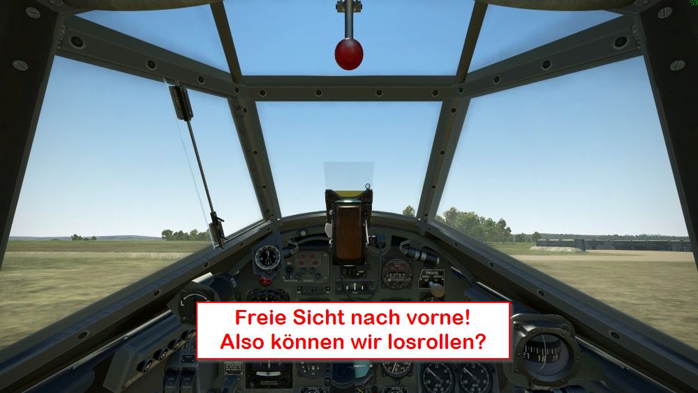
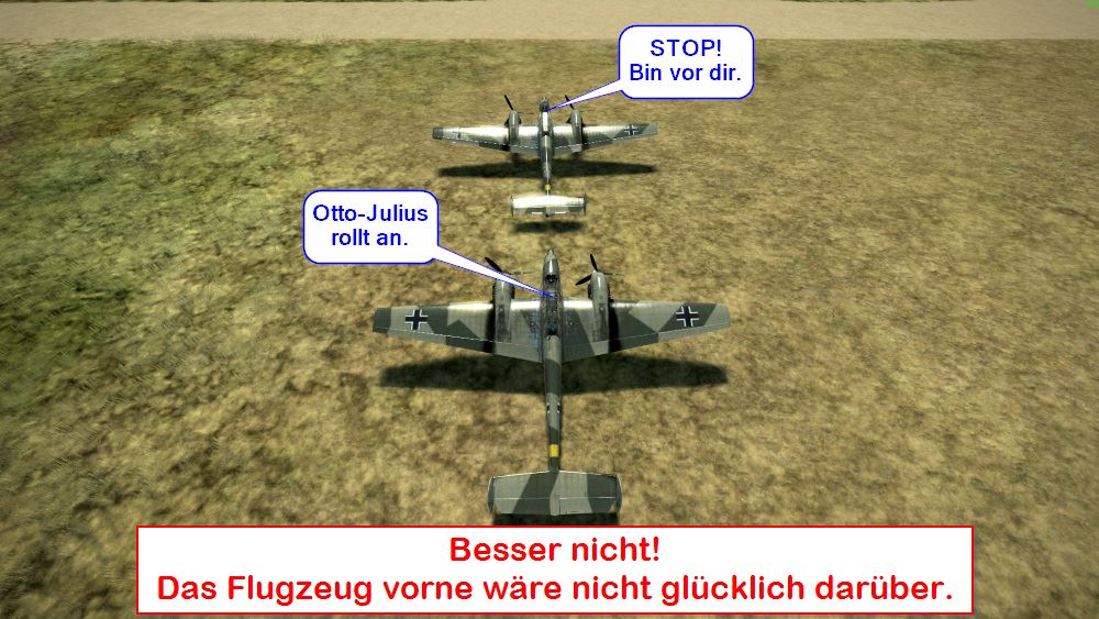
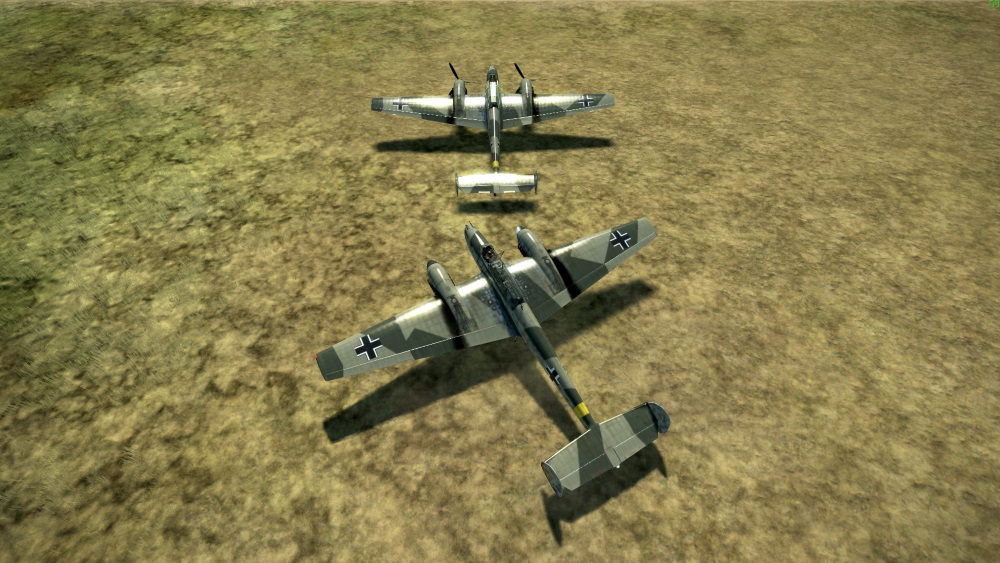
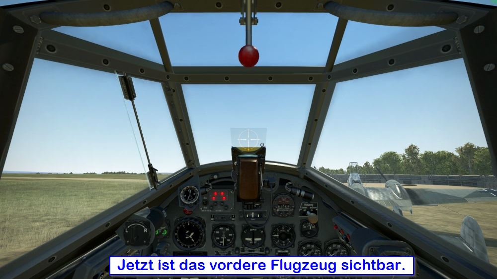
2.2. Lookout Before Taxiing
On aircraft with three-point landing gear and tail wheel, forward visibility is blocked by the engine. If another aircraft is standing directly in front of you, you cannot see it. Therefore, a frequent cause of accidents is that a pilot approaches and overlooks the aircraft in front of him. Then there is a break before the mission even started. This is very annoying on servers where the number of planes is limited.
In reality, the pilot can already see when boarding whether another aircraft is in front of him. The problem is more likely to occur with virtual flying, especially if there is no pilot coordinating the traffic.
To avoid accidents it is important to lookout. There are the following methods:
- Use of external views,
- Adjust viewing height via TrackIR,
- Lean to the side with TrackIR,
- Yaw the aircraft.
- Request help.
Use of the Outside Views
This is of course the simplest method, but also the least realistic. In addition, the use of external views is prohibited on many online servers. Therefore one should also master the other methods.
Adjust Viewing Height via TrackIR
This method is slightly cheating and does not work with every flight simulation. As an example the Bf 110 E-2 in "IL-2 Great Battles" difficult to steer in zigzag lines when taxiing on the ground.
- You sit upright on your chair and have your TrackIR centered normally.
- Now duck a little and press the key combination to re-center.
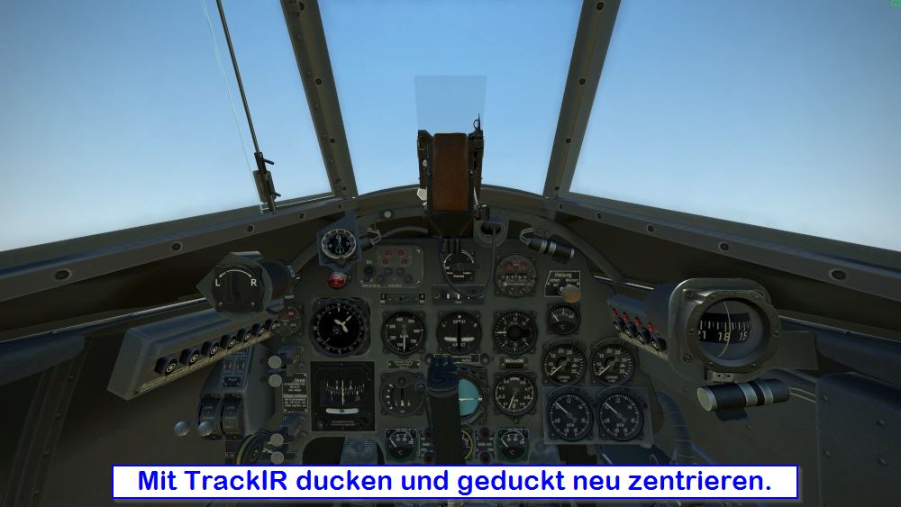
- When you're sitting straight again, your line of sight is increased enough to look over the nose.
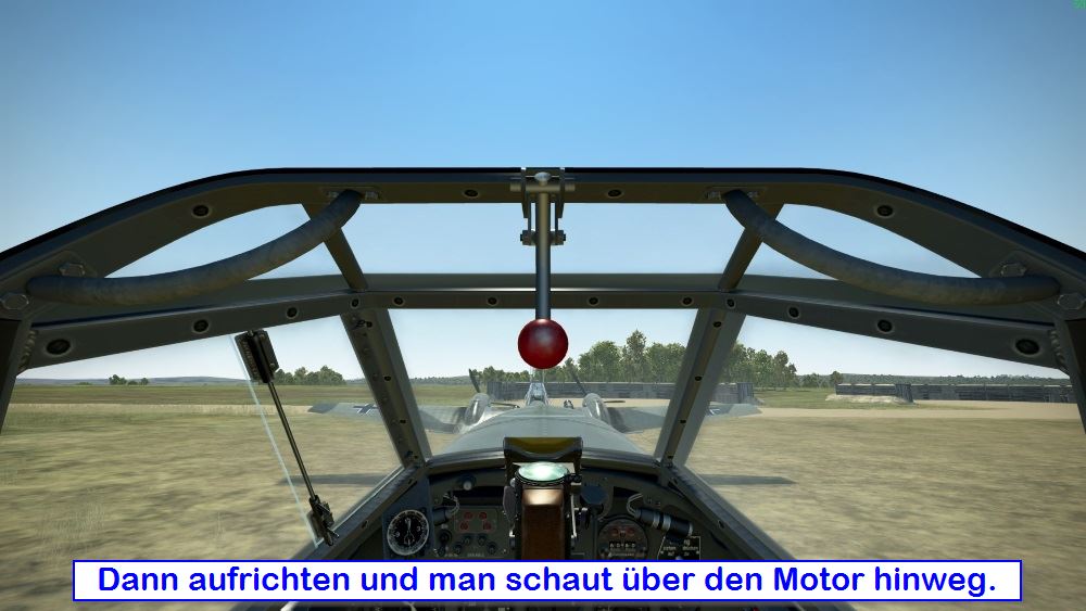
- This only works if the cockpit is open!
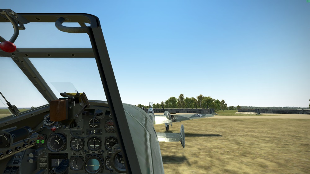
Lean to the Side with TrackIR
You just lean over to the left or to the right with the cockpit open again:
Yaw the aircraft
If you don't have TrackIR or if the simulation doesn't allow the above two methods, you have to yaw your plane:
- Apply one brake only, if necessary apply the same rudder.
- Cautiously accelerate until the aircraft yaws slowly.
- Reapply both brakes.
Once it Is clear ahead of you straighten the plane back to the runway heading by performing the same steps in the opposite direction.
Request Help
Ask other pilots who can see your location to confirm if everything is clear in your blind spot.
2.3. Ground Taxi
Placeholder
Topic: Speed, WEg distance, changed distance due to unforeseeable events, stop instruction, light guidance
Some Notes by Gosling Speed - Fast walking pace 15km/hr max
WEg Distance - ???? What is that? Wing Distance?
Unforeseeable events - Give a good separation
Stop instruction - Hold before any runway and look into the approach direction before linking up or crossing. (I say out loud “Clear on approach, threshold, runway and depature lane” every time I line up)
Light Guidence - Use Position Lights, Red Anti-col and Taxi / Landing Lights.
Tail Wheel Aircraft should zigzag while taxiing
USN (F-18 etc) Taxi Policy - Taxi in Left or Right half of taxiway. Subsequent aircraft taxi in alternate halves.
Braking - In WWII aircraft, with differential brakes, the braking power is reduced by half if the rudder pedals are displaced. Braking in a straight line is the most effective.
USN (F-18 etc) Hold Policy - Hold at 45 degrees to the taxiway to allow more aircraft to fit in at the hold.
2.4. Zigzag Taxiing
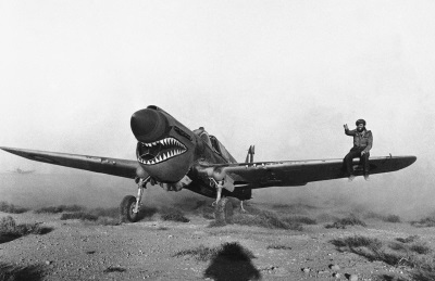 In the chapter "Lookout Before Taxiing" we have already described this. Depending on the type of aircraft, forward visibility can be very restricted. This of course causes problems when taxiing on the ground. US Ground Crew often sat down on the wing to guide their pilots in the right direction. Of course we don't have that in our simulations. As already described, you can make use of the outside views, the adjustment of the point of view or the like. But if nothing else, you should zigzag along the taxiway.
As you can see from the red arrows in the picture, you taxi cross the taxiway in a zigzag pattern. You look through the side window along the taxiway. The angle has to be chosen so that you have enough view forward and also stay on the taxiway. If you are sure, choose a less turn angle to move faster. If you want to check where you are and whether the path is clear, you choose a greater angle.
2.5. The Hold
 Before taxiing onto the runway, the aircraft is stopped. The taxi clearance is valid to the HOLD for the runway and not onto the runway.
You have to imagine it like there is a STOP sign in front of the entrance to every runway. On modern airfields there is indeed a clearly visible stop line. With some aircraft types (and simulations), there is a checklist to complete at the Hold. These configure the systems to minimise time on the runway before takeoff, so as not to block it longer than necessary.
The most important thing, however, is the lookout into the approach lane (airspace) and on the runway for other aircraft. Both have to be clear before you taxi onto the runway, unless ou are completing a formation takeoffs with other players. If another pilot controls the movements of all the individual planes and gives permission for the formation to enter and align on the runway (line-up), you should still look out for other traffic. Depending on the simulation (e.g. with DCS), you may have to radio the ATC (Tower) to get clearance to enter the runway.
If there are no Stop Markings (Yellow Line) you can hold relatively close to the edge of the runway. If the runway is very narrow, you may need to keep more distance. This is for your own protection. If, for example, a bomber is landing with its wings protruding beyond the runway and you are standing very close to the edge of the runway, a collision could occur. The same applies if another pilot makes an emergency landing with limited control and touches down too far to one side.
The picture below shows an example. Here the middle of the turn arc is used as a safe holding point.
2.6. Circuit Pattern
The aerodrome circuit is a standardised procedure for the arrival and departure of aircraft flying under Visual Flight Rules (VFR) and landing at an aerodrome which does not have air traffic control (air traffic controller). The following is achieved with the aerodrome circuit:
- The traffic flow for taking off and landing aircraft is orderly.
- The pilot gets an overview of the airfield, its status, environment and other airspace participants.
- He uses a known procedure that gives him time to make all the preparations for landing, and the sequence become natural after some practice.
- The radio messages made by other airspace users make him aware and allow him to react accordingly.
The International Civil Aviation Organization (ICAO) has defined the Standard Aerodrome Circuit. In foreign countries, this is usually regarded as the standard. In some countries airfields usually have special approach charts in addition to the normal approach charts on which the flight path and the height of the aerodrome circuit are marked.
For a beginner flying the circuit well is a challenge, because many steps have to be conducted. However, this course circuit training is an important part of the overall pilot training. All the important flying skills need to be used. When a pilot familiarizes himself with a new aircraft, the first flight exercise is always to fly circuits. The routine learned there can save your life in an emergency.
If there is no other explicit arrangement, the course usually flown anticlockwise (actually it is generally away from habitation). The shape is rectangular ashore and race track at sea.

The circuit consists of five parts:
- Take-off and Up Wind
- Cross Wind
- Downwind
- Base
- Final
Start and Up Wind
This is the first phase of the circuit. As soon as the landing gear breaks contact with the ground, the climb begins. The runway track is maintained on the Up Wind leg.
- When at a safe climbing speed the landing gear is retracted. This reduces the drag and leads to an improved climb.
- At a height of 500 ft AGL (Above Ground Level), i.e. approx. 150 m above ground, the flaps are retracted and the landing light switched off.
- The minimum distance to the runway before turning into cross take-off is 1.5 km. However, this is not enough for fast aircraft. Therefore maintain Up Wind for at least 30 seconds. Then turn Cross Wind or, if departing, turn on heading for your destination airport.
Cross Wind
The Cross Wind course is 90° to the runway course. Hence it’s name. One flies across the oncoming wind for that runway. You continue to climb to the given circuit altitude (usually 1,000 ft AGL, approx. 300 m). The course in Cross Wind is maintained until the airfield in your 8’Oclock (or 4 O’clock) (for approx. 1.5 km). Then turn into the Downwind.
Downwind
Downwind is the direction opposite to the runway approach, the circuit height is maintained and the speed normally between 60 and 150 kts depending upon the type of aircraft. This should be well within the limiting speed for the flaps and landing gear. Those limits depends on the aircraft type. Also the indication, how far the flaps should be extended, is different depending on the aircraft. By extending the flaps the lift is increased, but also the drag is increased. The upward movement may have to be counteracted in order to maintain circuit altitude so adjust attitude and trim. Depending on the speed, the higher air resistance can be used for braking or must be compensated by more engine power. During the Downwind the Before Landing checks are completed including:
- Landing gear ... Down
- Flaps ... As Required
- Landing Lights ... On
The Downwind is parallel to the runway on the opposite direction (i.e. 90° offset from the Cross Wind and 180° offset from the runway course). This course is maintained until the runway is visible at about 45° angle (7 to 8 O’clock) to the rear (left shoulder of the pilot). Now make a descending turn into the Base Leg.
Base Leg
On the Base Leg reduce altitude (and reduced speed to the approach speed - this may be weight related). Select flaps to fully Down (if not already). Then continue descending and turn by 90° To be at to approximately 500ft (to 150 m) on the Final Approach.
Final Approach
In the Final Approach, begin a continuous descent to the touchdown point. This is judged by noticing that the threshold stays in the same place in the windscreen. Maintain the approach speed so that the aircraft does not become too slow and unstable or too fast at touching down. This is achieved by maintaining a steady attitude. The descent rate must be suitable for the aircraft not touch down too hard or overshoot the touch down point. This is achieved by adjusting power.
Some airfields have an optical device that provides information for the correct glide path angle. The final approach leads to touchdown.
Touch-and-Go
If you want to do more than one circuit in a row, Touch-and-Go by not braking the aircraft once the landing gear touches down. Instead, roll for about 5 seconds and then increase the throttle to takeoff power, retract the flaps to the take-off position and, without stopping, the aircraft can takeoff again.
Joining an Airfield
Five minutes before arriving in the airspace of the destination airfield, announce yourself by radio. As soon as you arrive, you will enter the Downwind.
Special Features
Fast aircraft maintain their course longer after take-off until they turn into cross take-off. This also applies in the Downwind until turning into the Base Leg. As a rule, approx. 30 seconds after passing the runway threshold is sufficient distance from the runway.
Further information
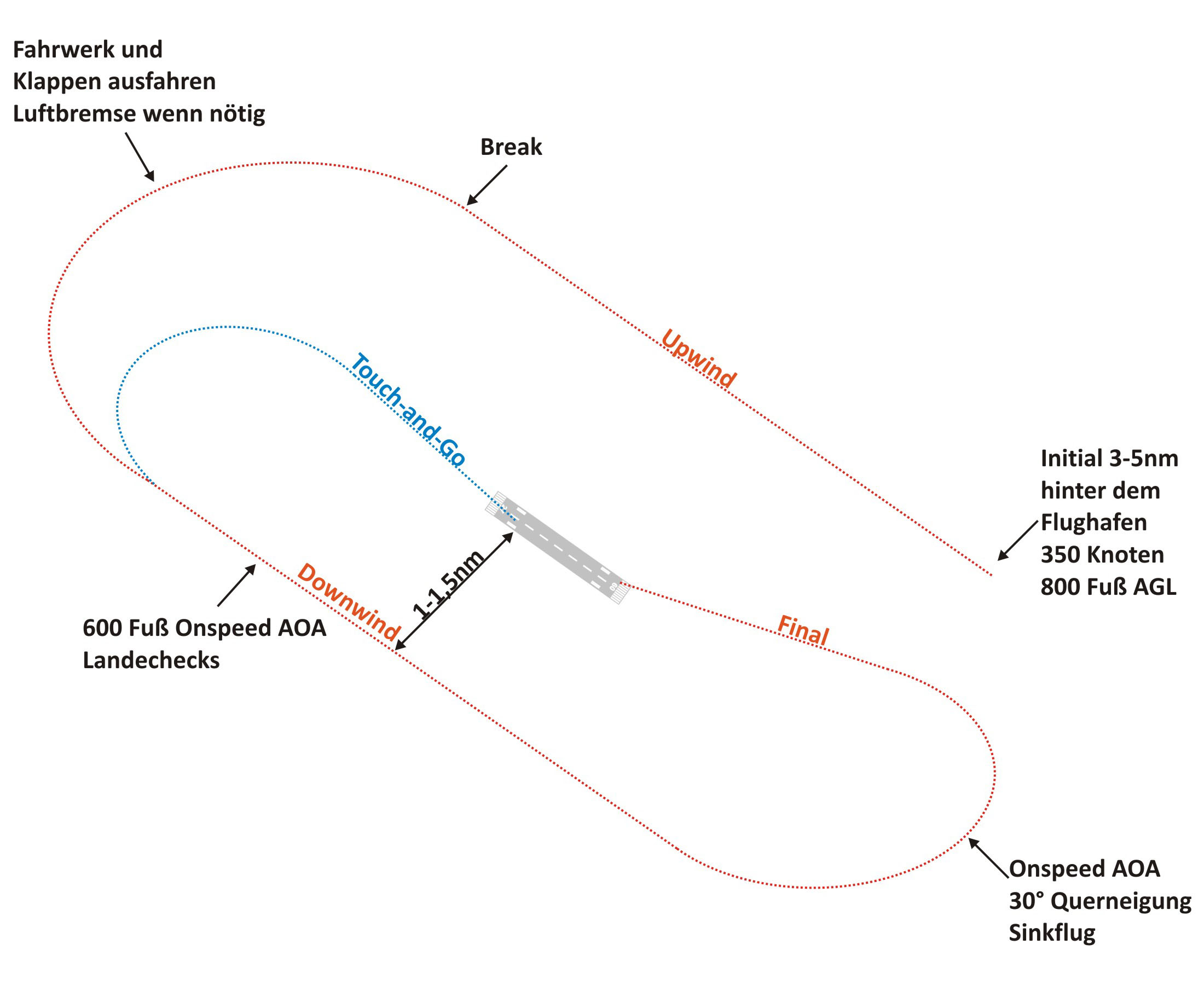
2.7. Overhead Brake
Eine besondere Form der Platzrunde ist der sogenannte "Overhead Break".
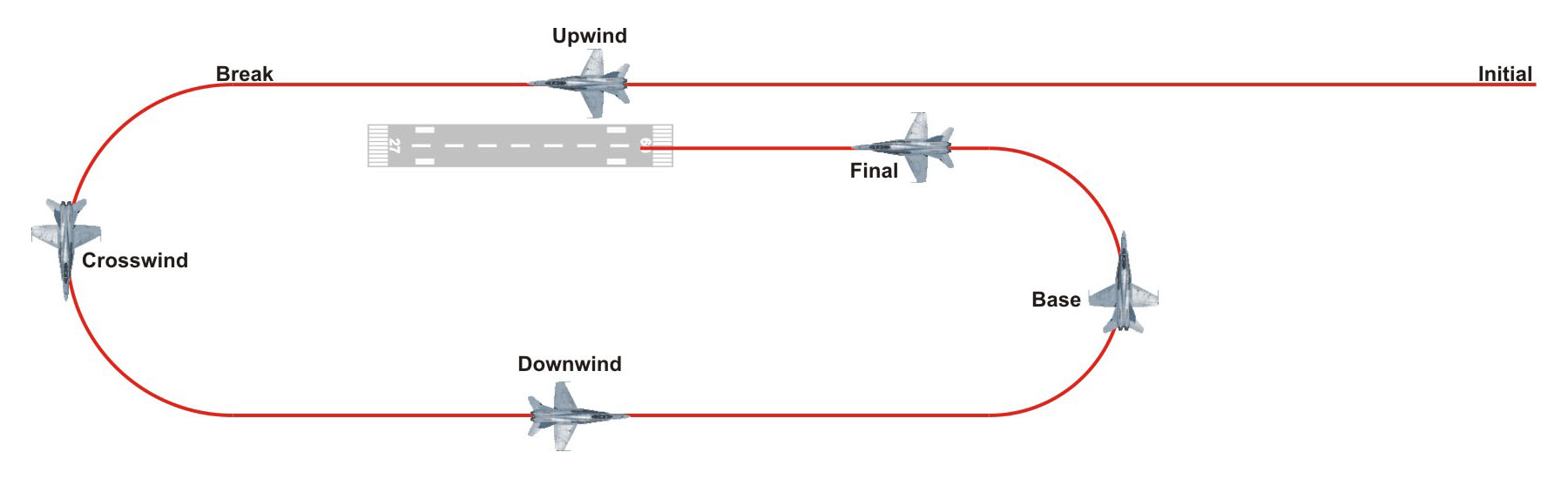
Diese Form der Platzrunde wird bei mordenen Kampfjets verwendet. Sie beschleunigt das Landeverfahren und verringert die Anzahl der nötigen Funksprüche. Durch die enge Kurve im Brake wird das Flugzeug stark ausgebremst. Dies führt dazu, dass die Geschwindigkeit zum Ausfahren des Fahrwerks bereits am Anfang des Downwinds erreicht wird ohne die Luftbremse dabei verwenden zu müssen. Fliegen mehrere Flugzeuge in einer Formation einen Overhead Brake, dann wird der Break gestaffelt durchgeführt. D. h. nachdem der Flight Lead eindreht wartet jeder nachfolgende Flieger 3-7 Sekunden (Länge kann durch Handzeichen koodiniert werden) nachdem sein Vordermann abgedreht hat und dreht dann selbst in den Break ein. Das ergibt im Landeanflug einen ausreichenden Abstand für eine kontrollierte und sichere Landung der Gruppe.
Die Höhen und Geschwindigkeiten für den Overhead Break variieren je nach Flugzeug und örtliche Vorgaben.
Initial Point
Die Platzrunde beginnt am Initialpunkt der sich 3-5 nm vor der Landebahn befindet. An diesem Punkt soll man eine definierte Höhe und Geschwindigkeit haben (siehe Checkliste des Flugzeugs). Man fliegt mit dieser Höhe und Geschwindigkeit leicht rechts versetzt parallel zur Landebahn an.
Upwind
Beim Upwind fliegt man rechts versetzt zur Landebahn am Flughafen vorbei. Dabei wirft man einen Blick auf den Flughafen, um eine Übersicht über die Umgebung zu bekommen.
Break
Sobald du ca. 1 nm am Flughafen vorbei bist, leitest du den Break (180° Kurve zum Crosswind) ein. Du nimmst den Schub komplett zurück und fliegst eine Linkskurve mit 1 % der Fluggeschwindigkeit als Kurvenbeschleunigung. D. h. bei 350 Knoten mit 3,5 G. Während du langsamer wirst, reduzierst du auch die G-Beschleunigung. Also bei 300 Knoten 3 G usw.
Crosswind (Querabflug)
Beim Crosswind (nach ca. 90°) wird das Fahrwerk und die Landeklappen ausgefahren. Die Kurve wird währenddessen fortgesetzt, bis du entgegengesetzt zur Landerichtung (180°) im Downwind fliegen.
Downwind (Gegenanflug)
Im Downwind angekommen, reduzierst du Geschwindigkeit für den passenden AOA. Außerdem gehst du die Landecheckliste durch und trimmst die Maschine für die Landung aus.
Base (Queranflug)
Wenn du an der Landebahn vorbei bist und die Landeschwelle auf deiner 7-8 Uhr-Position hast, drehst du wieder nach links ab. Diesmal mit 30° Querneigung und On Speed AOA, also Landegeschwindigkeit und passenden Anstellwinkel. Während des Queranflugs behältst du die Landebahn im Auge, um bei Bedarf etwas korrigieren zu können, damit du die Landebahn genau anfliegst.
Final (Endanflug)
Nachdem du den Queranflug verlassen hast, befindest du dich im Endanflug. Du gehst in den Sinkflug, prüfst deinen Gleitweg (3°) und verbesserst diesen bei Bedarf. Der restliche Endanflug ist identisch mit dem Kapitel "Standardlandung".
Touch-and-Go (Aufsetzen und Durchstarten)
Wenn man mehrfach hintereinander den Landeanflug üben möchte, dann bedient man sich des Touch-and-Go-Verfahrens. In diesem Fall gibt man direkt nach dem Aufsetzen wieder vollen Schub, hebt ab und geht in den Steigflug. Man steigt auf Platzrundenhöhe und dreht wieder nach links in den Downwind. Von da aus wird der Landeanflug erneut durchgeführt.
Video
Hier ein Video des Ablaufs. Leider gibt es das nur in englisch:
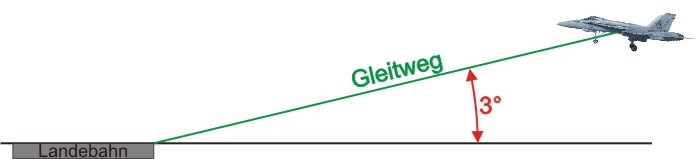
2.8. Standard Landing from a 3° Glidepath
A little basic knowledge of the landing approach is necessary for you to complete a successful landing. Many airplanes are designed to approach the airport on a glidepath of 3°. Approximately 320 feet per nautical mile. So, it is possible to calculate which height you should have at which point on this 3° glide path. It is therefore possible to fly into the 3° glide path at any range at the approximately suitable altitude. During landing exercises you will quickly notice that there is a clear difference between how far you are from the airfield and how high you are. Therefore it is necessary to define a standard case. This is the 3° glidepath. That is why it is the first step for every landing to fly the aircraft as close as possible to this optimal case.
Glidepath
The correct glide path for landing is 3°. If it is less than 3° there is a possibility that we will land before the threshold. If the glide angle is too steep our sink rate will be too high and we could damage the landing gear because we put the aircraft down too hard.
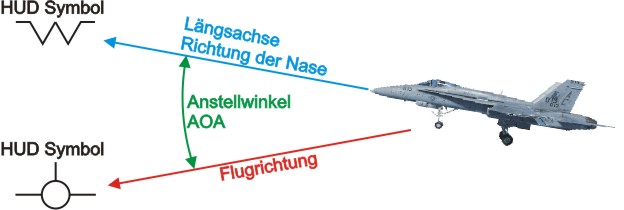
Inclination angle
The Angle of Attack (AOA) is the angle between the flight direction and the longitudinal axis of the aircraft. This angle should be between 7.4° and 8.8° during landing. The angle of attack is directly related to the airspeed.
Airspeed
The airspeed must be selected so that the appropriate angle of attack is achieved. In addition, the speed depends on the weight of the aircraft. Basically the following statements can be made.
Greater weight = Higher landing speed
Lower airspeed = Higher angle of attack.
Example: For missions from the F/A-18C basic course you should calculate with approx. 140 knots.
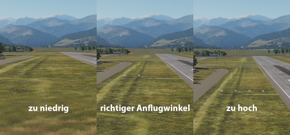
Precision Approach Path Indicator (PAPI)
Many airports have 4 signal lights (PAPIs) next to the runway touch down point which display your glide path. Each light has a white segment and a red segment. Each is anglesd slightly differently so that they display as follows.
2x white and 2x red would be a correct glide path. As you can see in the following picture. If all are red you are too low and if all are white you are too high.
Easy to remember is:
- ALL ARE WHITE - "Check your height" = too high
- RED AND WHITE - "You are right" = correct height
- ALL ARE RED - "You are dead" = too low